![]()
|
|
|||||||||||||||||||||||||||
|
OEM TRANSDUCER–FVCC-VRPM Precision Multi Configurations Differential Input Frequency to Voltage or Current (0-20mA)Converter (FVCC) Industrial Super Transducer. With Direction & +VRPM functions, Zero and Span adjustments.
The TRANSDUCER–FVCC-VRPM frequency to voltage converter is a pulse signal 1Khz or 10KHz frequency to (Proportional) voltage super transducer board with unique output voltage polarity based on input direction, for CNC, HVAC (Heating, Ventilation and Air Conditioning), electro-hydraulic and BLDC servo motor; actuator, dampers, bleed pilot valve, globe valves, butterfly valves, plug valves, dampers and more.
The TRANSDUCER–FVCC-VRPM board is designed to perform precision frequency to voltage or current with direction conversion (transducer). If used properly, it will eliminate the need for an expensive board, which would otherwise be needed to carry out the same tasks.
The TRANSDUCER–FVCC-VRPM is easy to install, setup, and operate. If you want to do professional frequency to voltage or current or RPM measurement related functions, The TRANSDUCER–FVCC-VRPM offers the features you need. It can be mounted easily via four 0.125" mounting holes using 4-40 and / or 6-32 screws. |
|
||||||||||||||||||||||||||
|
Simply connect the board to power connect your frequency pulse source 0 to 1KHz (or 0 to10KHz) to the input and it will convert it to 0 to 10V connect the direction input to ground and it will convert it to 0 to -10V (auto-polarity change). Set the board to current output and you will get 0-20mA.
Note: 1HZ = 60RPM therefore 1KHz => 60000 RPM and 10KHz => 600000 RPM. We chose output of 0 to 20mA or 0 to +/-10V because standard PLC and industrial interface excepts transducers with 0 to +/- 10V input. Whoever we also have +/-5V and +/-1V models.
Our TRANSDUCER–FVCC-VRPM OEM Frequency to Voltage Converter (FVC) with automatic direction function module transducer is designed to convert a continuous series of digital pulses (frequency) into an analog voltage. The board is ideal for a close loop control of a motor shaft. The input is designed to accept low level (as low as +/- 60 mV P-P) pulses from magnetic pick-ups or high-level square wave signals from a shaft encoder (as high as +/- 40 V P-P). Model depended; the output voltage is positive (0 to 10 VDC) or negative (0 to 10 VDC) with a magnitude proportional to the input frequency signal. This FVC board may be used to provide a unidirectional analog velocity signal that is directly proportional to the output from an encoder connected to a rotating shaft. The output maintains a signal linearity and drift too less than 0.3% with temperature drift of less than 0.05% per degree centigrade with a very low ripple, less than 30 mV P-P at 10 KHz. Each frequency to voltage converter module includes controls to set the output signal Zero and Span. Where the Zero output sets for zero input frequency (CW incises). And Span output sets to maximum input frequency (CCW incises). The board operates of 3 wires +/- 15 VDC power supply. The board’s Molex cage-up Terminal-Block makes it easy to connect to external connections and controls
The TRANSDUCER–FVCC-VRPM Module delivers analog 0 +/- 10 VDC (or 0 to +/- 5 VDC) outputs proportional to input pulse rate (frequency) and direction. Where it accepts variable pulse rate inputs from a variety of sensors including magnetic pick-ups, with maximum linearity. It the ideal board for supplying velocity feedback in bi-directional closed loop speed control systems. Work directly with our 3 phases Brushless motor drive (AMP) and controller such as Pivot-Pimer/Pioneer/Power/Supprimmer/Extreemer.
The Bipolar (Bi Polarity) Frequency to Voltage Transducer Direction function: The analog output voltage polarity automatically changes to "FORWARD" (0 to VX) and "REVERSE" (0 to -VX). NO NEED FOR ”POLARITY SELECT VIA HEADER SHORTING JUMPER BAR”! Where FORWARD, the analog output voltage polarity will be positive and "REVERSE" The analog output voltage polarity will be negative. The polarity of the output voltage changes automatically for a specific rotation direction set by the direction input of the transducer.
The Board operates on the frequency content of a Sinusoidal, Triangular, or Square waveform. Typical transducers include:
For fast response of Board outputs, it is important that the transducer
be located toward the high-speed end of the drive train. For slow shaft
speeds, the transducer must be capable of delivering a high number of
cycles or pulses per revolution. The transducer should also be capable
of delivering a usable output for the entire speed range through maximum
speed. The following formula is convenient for relating machine speeds and sensor frequency output:
Where;
Super performance in is class; The Industrial board Zero and Span adjustment allows the unit to deliver full-scale output voltage for any input frequency within the limits of frequency range rating. It will provide an ultimate combination of fast response and low ripple.
This industrial grade transducer includes super output signal linearity and drift too less than 0.3 % as the ambient temperature and or input power supply voltage and are varied over the specified range.
The TRANSDUCER–FVCC-VRPM circuit board is structure-utilizing bended throw-holes components that mean no problems down the road do to movement, (due to the natural use of the board in moving parts environment). No SOLDER MASKED component falling of the board during heat and movement! All external connections are made via “Molex cage-up type” terminal block.
The TRANSDUCER – FVC-DDZS transducer board is an accurate, linear, and an efficient way to convert industrial standards frequencies 0 to 1KHz, 0 to 10KHz into +/- 10V industrial standards or +/- 5V output voltages signals.... See below table "frequency to voltage industrial standard configuration models".
|
|||||||||||||||||||||||||||
|
Super precision Fervency-to-Voltage Transducer/Converter/Transmitter
TB1:
Pins 1 & 2 Power 24V or 28V AC or DC
Pins 3 & 4 Power output for driving external Hall Effect sensor (+VRX = 15VDC 20mA Max)
Pins 5 & 6 Differential (INH and INL) or Single Ended (SE) Input Frequency.
Pins 3 & 7 Direction "Open" or "high" for positive output voltage (0 to 10VDC), "Short to ground" or "low" negative output voltage i.e. 0 to -10VDC
Pins 8 & 9 Output Voltage (0 to 10V DC or 0 to -10V DC or 0 to 5V DC or 0 to -5V DC) Direction depended or 0-20mA.
Pins 8 & 10 Output Voltage ("VOUT" * 1.5) i.e. 8 poles BLDC motor controller output 0-1.5V represents 0 to 15000 RPM.
ZERO:
Precise calibration 0Hz - input 0V or 0mA output multi-turn trimmer Zero adjustment.
SPAN:
Precise calibration 1KHz or 10KHz input +/-10VDC (or +/- 5VDC) or 0-20mA output multi-turn trimmer Span adjustment.
JP1:
Fervency select A. 1KHz B. 10KHz.
JP2:
Ripple select A. 1KHz B. 10KHz.
JP3:
Output select Voltage +/-10V or current 0-20mA
Frequency to Voltage industrial standard configuration models:
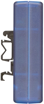
Mounting Option
Simply snap the Din-Rail mounted enclosure into your NEMA 4 box (enclosure) for watertight applications
EID-1593LTBU Translucent blue ABS plastic instrument enclosure with Din-Rail mounting options, side view
Plastic enclosure and Din-Rail-clip are sold separately (for demonstration only).
TRANSDUCER–FVCC-VRPM Features
Can be customized to accommodate your input or output frequency and voltage requirement.
Industrial
Standard output of 0 to +/- 10V makes the TRANSDUCER ideal for use
with PLC and BLDC.
Linear voltage output. On board trimmer facilitates precise Zero calibration of output current (0Hz input to 0.000 output)
Specifications
|
|||||||||||||||||||||||||||
|
Pricing
* Prices, SKU#, P# specification and colors are subject to change without notice. |
|||||||||||||||||||||||||||
|
Description |
SKU # |
Price |
|||||||||||||||||||||||||
|---|---|---|---|---|---|---|---|---|---|---|---|---|---|---|---|---|---|---|---|---|---|---|---|---|---|---|---|
|
TRANSDUCER–FVCC-VRPM Frequency (0V to 1KHz or 10KHz) to voltage (0V to +/-5V) super transducer (converter) with Direction, Zero, Span and terminal-block (10 positions). |
EID-CONVER-TER-FVCC-D110-5PN-10TB |
Call/e-mail |
|||||||||||||||||||||||||
|
TRANSDUCER–FVCC-VRPM Frequency (0V to 1KHz or 10KHz) to voltage (0V to +/-10V) super transducer (converter) with Direction, Zero, Span and terminal-block (10 positions). |
EID-CONVER-TER-FVCC-D110-10PN-10TB |
Call/e-mail |
|||||||||||||||||||||||||
|
Modified Translucent blue ABS Plastic Instrument enclosures option |
EID-1593LTBU |
$15.75 |
|||||||||||||||||||||||||
|
Din rail mounting mounting kit option |
EID-1427DINCLIP |
$4.44 |
|||||||||||||||||||||||||
|
|
|||||||||||||||||||||||||||