![]()
|
|
||
|
|
||
|
INTERFACER–QUAD-ADR4-SMT. Adjustable voltage/current sensitive quad relay control Board.
The INTERFACER-QUAD-ADR4-SMT board is designed to perform 4 relays switching function based on two set points voltages or currents levels "PICK UP" and "DROP OUT"
1. Per relay (Chanel) Differential ("Drop Out") voltage set point
2. Per relay (Chanel) Trip set point ("Pick Up")
The board can accommodate three industrial inputs configurations:
1. Input current 4-20mA (or 0-20mA)
2. Input current 1-5mA (or 0-5mA)
3. Input current 10-50mA (or 0-50mA)
4. Input voltage 0-5VDC
5. Input voltage 0-10VDC (or custom see Application note #108)
6. Input voltage 0-15VDC
7. Input voltage 0-20VDC
8. Input voltage 0-30VDC
9. Input voltage 0-60VDC |
||
|
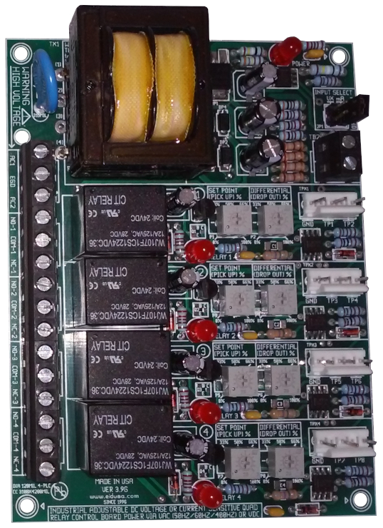
Voltage sensitive quad relay board shown above OEM in Trough-Hole configurations
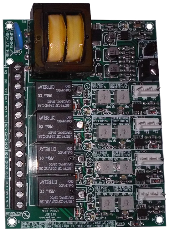
Voltage sensitive quad relay board shown above OEM in SMT configurations
If used properly, it will eliminate the need for expensive boards, which would otherwise be needed to carry out the same tasks.
The INTERFACER-QUAD-ADR4-SMT-SMT is easy to install, setup and operate. If you want to do professional relay switching via setting of voltage or current, The INTERFACER-QUAD-ADR4-SMT-SMT offers the features you need.
As mentioned above, the board can be configured to accept input signals of 0-60V, 0-30V, 0-20V, 0-15V, 0-10V, 0-5V or 1-5mA, 4-20mA or 10-50mA.
Mounted easily via four 0.125" mounting holes.
Setting the board is simple Just follow these easy steps
1. Connect the board to 120VAC
2. Set the board via jumper provided to the desired input configuration (10V, 5V or 4-20mA).
3. Connect your voltage or current signal to the input. Set the each reference point until its relay turns on (LED will light up).
4. Adjust the input signal to the desired trip out point.
5. Adjust the each span trimmer until its relay turns off.
The board remembers input setting points and the relays will turn on and off based on them.
The board is ideal when an analog signal is required to switch 4 relay i.e. circulating pumps, recalculating fans, high and low fan speeds, humidifiers, pool chlorine feeding pumps, sensor level switching functions, differential switching controls, analog signal to relay on/off, analog signal voltage or current alarms and more.
Please drop us a line at HVAC@eidusa.com and let us know where you use this unique board. Or, of course, if you have any adjustments deemed important--and one of our engineers will be happy to help you achieve them. |
||
|
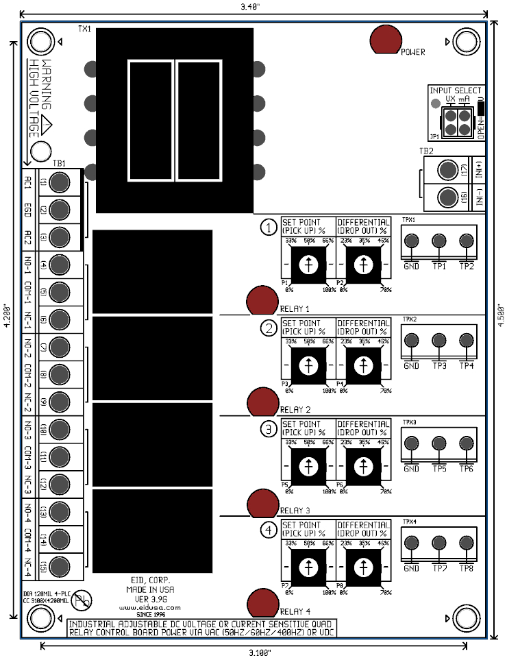
TB1:
Pins 1,
2 & 3 Power
120VAC
Pins 4, 5, 6 Relay 1 NC, COM & NC
Pins 7, 8,9 Relay 2 NC, COM & NC
Pins 10, 11,12 Relay 1 NC, COM & NC
Pins 13, 14, 15 Relay 2 NC, COM & NC
TB2:
Pins 16 & 17 Single Ended (SE) Input signal (Voltage/current)
Relay 1, 2, 3 & 4 SET POINTS (PICK UPS):
Per channel (relay) Set-point (Pick up) calibration trimmer "trip" adjustment.
Relay 1, 2, 3 & 4 DIFFERENTIAL (DROP OUT):
Per channel (relay) Differential (Drop out) calibration trimmer adjustment.
Test Point (TPX1 to TPX4):
Relay 1, 2, 3 & 4 SET POINTS (PICK UPS) & DIFFERENTIAL (DROP OUT) test point
Per channel (relay) Differential (Drop out) calibration trimmer adjustment.
JP1:
Input select: Voltage or current 0-5V, 0-10V, 4-20mA
RELAY LED
Per relay LED on indicator
POWER LED
LED, relay on indicator
INTERFACER-QUAD-ADR4-SMT-SMT Features
|
||
|
Specifications
|
||
|
Pricing
* Prices, SKU#, P# and colors are subject to change without notice. Additional 10% discount with student ID, USA only. |
||
|
Description |
SKU # |
Price |
|---|---|---|
|
INTERFACER-QUAD-ADR4-SMT-SMT 0-10 voltage to 4 relay on/off |
EID-INTERF-ECER-Q-ADR4-10S |
Call/E-mail |
|
INTERFACER-QUAD-ADR4-SMT-SMT 0 0-5 voltage to 4 relay on/off |
EID-INTERF-ECER-Q-ADR4-5S |
Call/E-mail |
|
INTERFACER-QUAD-ADR4-SMT-SMT 0 4-20mA current to 4 relay on/off |
EID-INTERF-ECER-Q-ADR4-4-20S |
Call/E-mail |
|
INTERFACER-QUAD-ADR4-SMT-SMT 0 0-15V, voltage to 4 relay on/off |
EID-INTERF-ECER-Q-ADR4-15S |
Call/E-mail |
|
INTERFACER-QUAD-ADR4-SMT-SMT 0 0-20V, voltage to 4 relay on/off |
EID-INTERF-ECER-Q-ADR4-20S |
Call/E-mail |
|
INTERFACER-QUAD-ADR4-SMT-SMT 0 0-30V, voltage to 4 relay on/off |
EID-INTERF-ECER-Q-ADR4-30S |
Call/E-mail |
|
INTERFACER-QUAD-ADR4-SMT-SMT 0 Comb. 0-5, 0-10 or 4-20mA to relay on/off |
EID-INTERF-ECER-Q-ADR4-COMBS |
Call/E-mail |
|
Adj. via 2 multi-turn trimmer (up to 20 turns) trimmers (option) |
EID-INTERF-ECER-QADR4-2MTTS |
Call/E-mail |
|
|
||